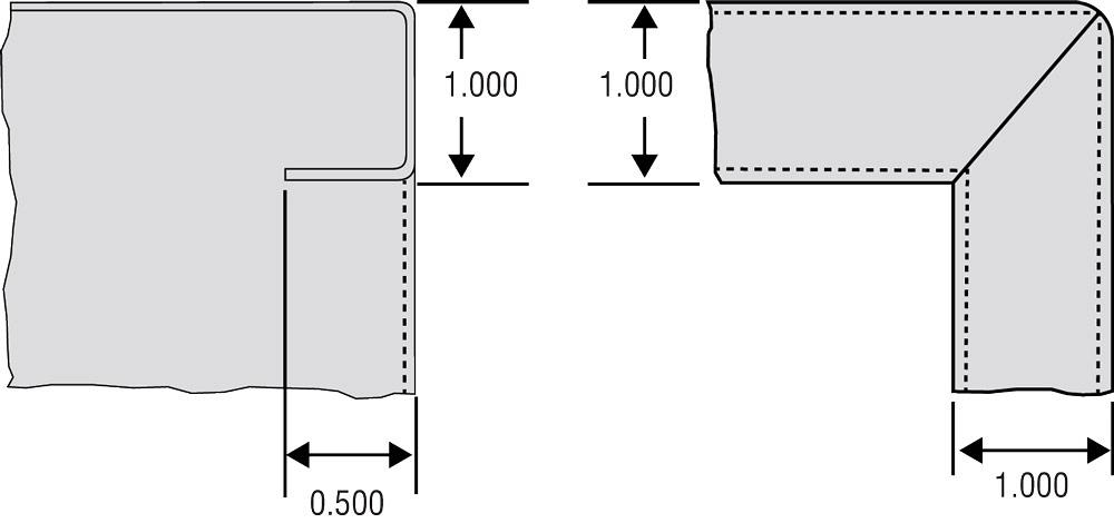
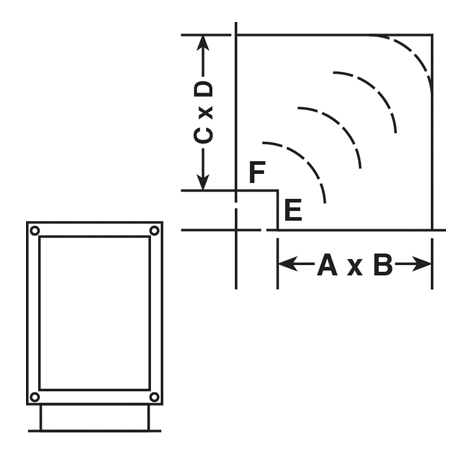
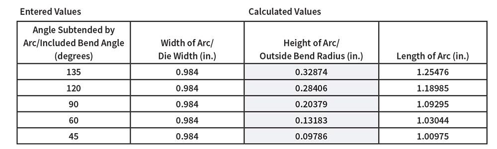
Calculating Layout Sheet Metal Corner Radius Bend

Layout And Forming Part One

Layout And Forming Part Four
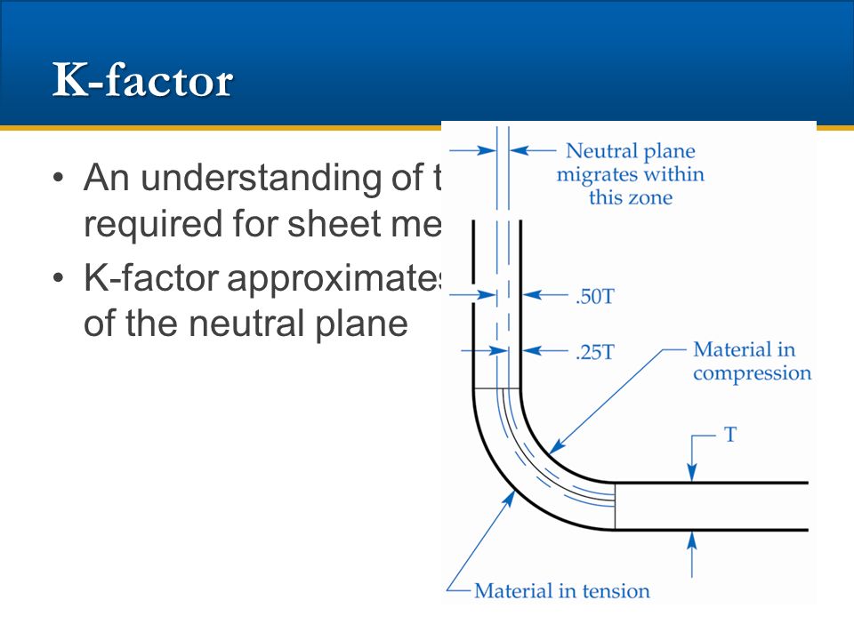
Analyzing The K Factor In Sheet Metal Bending
Following Dfm Guidelines For Working With Sheet Metal Machine Design

Online Calculator Of Sheet Metal Bend Deduction And Flat Length Gasparini Industries
Bend Allowance Sheetmetal Me
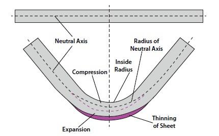
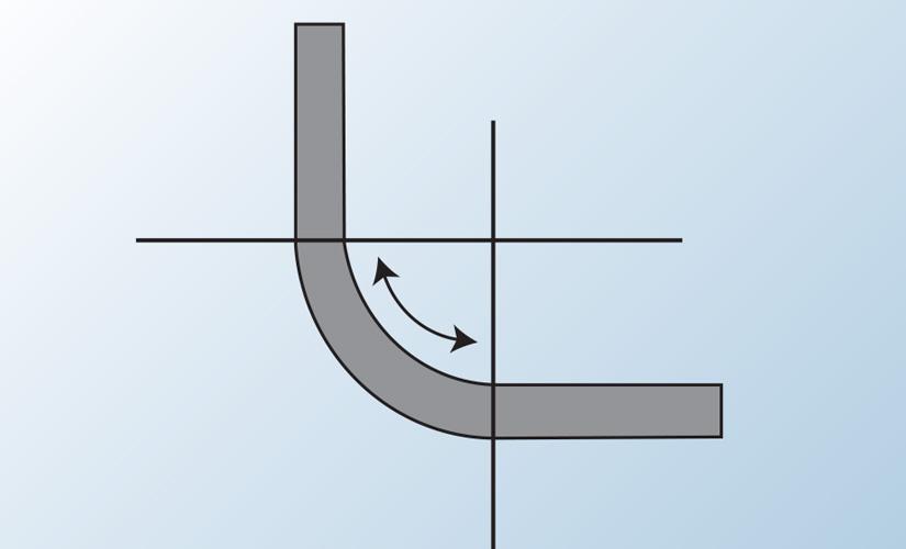
As this happens you gain a small amount of total length in your part.
Calculating layout sheet metal corner radius bend.

Pin On Mechanical Insulation

Press Brake Square Bend Deductions Sheet Metal Work Press Brake Metal Bending

Pin On Press Brake Tooling

Bending Basics How The Inside Bend Radius Forms Metal Working Metal Working Tools Welding And Fabrication
Sheet Metal Design The Definitive Guide Engineer S Handbook Machinemfg
Precision Sheet Metal Bending Bump By Bump
Minimum Versus Recommended Inside Bend Radius

Sheet Metal Options

Sheet Metal Bending Process Machine Sales Sheet Metal Sheet Metal Work Metal Bending

This Is A Great 9 Page Pdf Entitled Bendworks The Fine Art Of Sheet Metal Bending This Is A Basic Sheet Metal Metal Bending Sheet Metal Fabrication

What Sheet Metal Shops Wish You Knew Hems Jogs And Forming Tools

Sheet Metal Design Guide Geomiq
K Factor Sheetmetal Me
21 Precision Sheet Metal Parts 21 Precision Sheet Metal Parts Ppt Video Online Download

Solidworks Sheet Metal Gusset Tutorial Youtube Solidworks Sheet Metal Tutorial
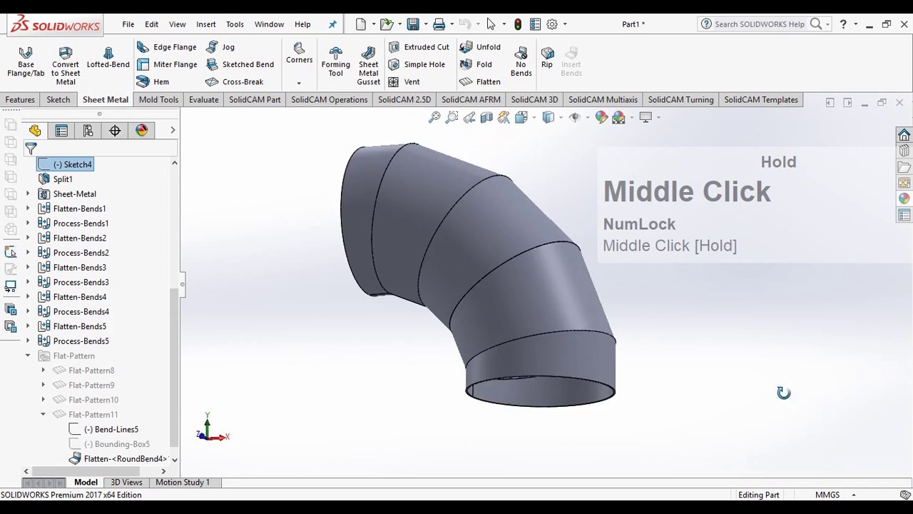
Development Steel Elbow Miter Bend Flat Pattern In Solidworks Sheet Metal Youtube

Sheet Metal Design Guide Bending Analyze From 8 Aspects Machinemfg

Sheet Metal Bending Hand Brake Machine Box And Pan Brake Sheet Metal Fabrication Sheet Metal Metal Tool Box
Https Encrypted Tbn0 Gstatic Com Images Q Tbn 3aand9gctf5 Nxksu4pilv5ywyfyl1 Wjg1jit Cavw4ekf14vx5cfm6oo Usqp Cau

Sheet Metal Drafting Chapter 3 Wikisource The Free Online Library

Inventor Sheet Metal Folds Youtube
Press Brake Bending And The Notch A Deeper Dive

Software Solutions For The Sheet Metal Industry

Bending Metalworking Wikipedia


Understanding Sheet Metal
Fabricating Precision Sheet Metal Aircraft Parts
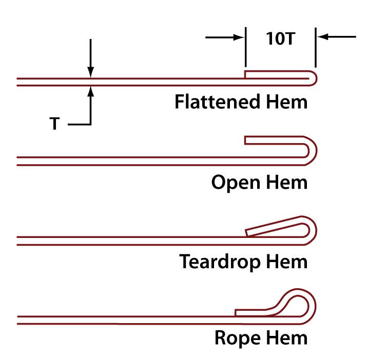
Press Brake Basics Bending Across The Hem

1a Drawing Task 16 Sheet Metal And Development Drawings Ppt Download

Bending Basics Why Do Die Angles Change Metal Working Tools Metal Working Sheet Metal Work

Unfolding Onshape Sheet Metal
2019 Solidworks Help Sheet Metal Gauge Tables
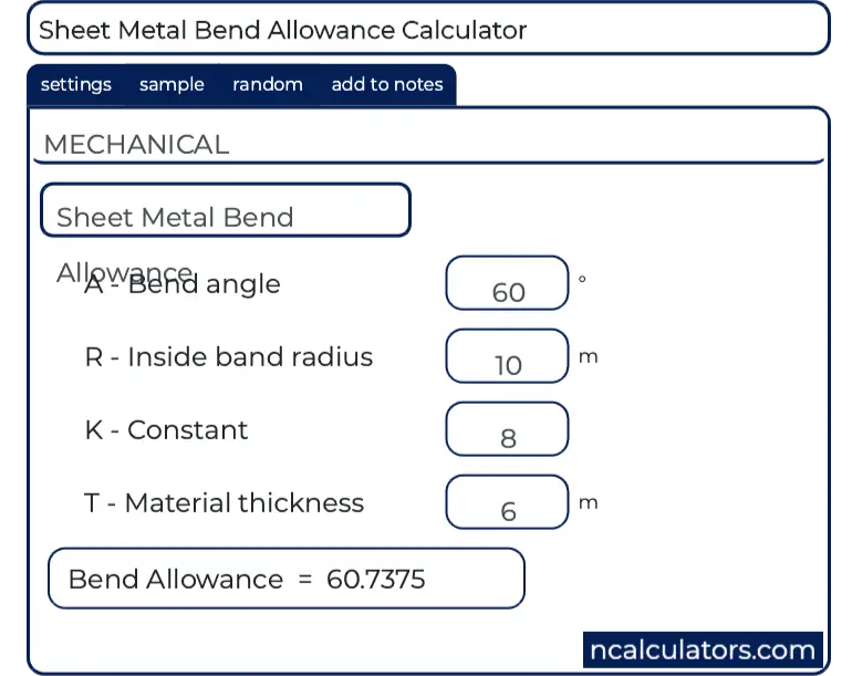
Sheet Metal Bend Allowance Calculator

Sheet Metal Bending Bending Definitions Metal Bending Sheet Metal Sheet Metal Fabrication
Solidworks Tutorial Sheet Metal Drawings Youtube
Shop Technology And 3 D Cad Sheet Metal Modeling
Press Brake Bending And Notching A Symbiotic Relationship
Square Throat Elbow Sheet Metal Connectors

Https Encrypted Tbn0 Gstatic Com Images Q Tbn 3aand9gcsynnzyz2gtoadyxf5csib5fsdf6lpsa0hy1q Usqp Cau

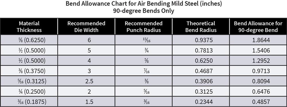
Press Brake Bend Allowance Chart Press Brake Allowance Chart Welding And Fabrication

Sheet Metal An Overview Sciencedirect Topics
Predicting The Inside Radius When Bending With The Press Brake

How To Bend Sheet Metal 13 Steps With Pictures Wikihow
Https Encrypted Tbn0 Gstatic Com Images Q Tbn 3aand9gcsiwqlcghpj4cp Mrtny4ounzafwlrd6vjaeues Dirhnv3qle4 Usqp Cau
Source : pinterest.com
