Catia Sheet Metal Extrusion

Catia V5 V6 Tutorial Sheet Metal Design Tutorial Part 02 Design Tutorials Metal Design Tutorial

Solidworks Sheet Metal Lofted Bend Youtube Sheet Metal Drawing Solidworks Sheet Metal

Catia V5 V6 Tutorial Sheet Metal Design And Manufacturing In Detail Sheet Metal Metal Design Metal

Pin On Solidworks

Solidworks 2013 Sheet Metal Metal Furniture Design Sheet Metal Drawing Solidworks

Solidworks Sheet Metal Tutorial Exercise Youtube Solidworks Solidworks Tutorial Sheet Metal

Set type to up to surface.
Catia sheet metal extrusion.

Solidworks Tutorial For Beginners Exercise 39 Youtube In 2020 Solidworks Tutorial Solidworks Technical Drawing

Pin On Solidworks

Solidworks Sheet Metal Forming Tool Exercise Youtube Solidworks Sheet Metal Solidworks Tutorial

I Want Sheet Metal Part Drawings To Practice Iam Not Able To Get From Google Can Anyone Pls Help Me Grabcad Sheet Metal Drawing Sheet Metal Sheet Metal Work

Esercizio 54 Sheet Metal Drawing Technical Drawing Mechanical Design

Pin On Solidworks

Solidworks Tutorial For Beginners Exercise 58 Youtube Solidworks Tutorial Solidworks Autocad Isometric Drawing

Pin Em Solidworks

Pin By Kemal Koyuncu On Kati Model Videolar In 2020 Solidworks Tutorial Solidworks Sheet Metal Drawing

Pin On Art

Turbine Catia V5 Gsd Training Fill Surface Close Surface Mechanical Design Autocad Isometric Drawing Gsd Training

Solidworks Tab And Slot Feature For Sheet Metal And Weldments Solidworks Sheet Metal Sheet

Using Solidworks Sheet Metal Functionality Create A B Size Drawing Technical Drawing Sheet Metal Drawing Mechanical Engineering Design

Pin On Homemade Cnc

Solidworks Tutorial Sketch Sheet Metal Screw In Solidworks Solidworks Tutorial Solidworks Solid Works

Solidworks Tutorial For Beginners Exercise 24 Youtube Solidworks Tutorial Solidworks Workout For Beginners

Solidworks Tutorial For Beginners Exercise 28 Youtube Solidworks Tutorial Solidworks Tutorial

Solidworks Tutorial For Beginners Exercise 62 Youtube Solidworks Tutorial Autocad Tutorial Autocad Isometric Drawing
Https Encrypted Tbn0 Gstatic Com Images Q Tbn 3aand9gctcfati9gmhvsgtoaxn Axseklzril09g8 Mjvtpdfefyq6y 4j Usqp Cau

Solidworks Tutorial For Beginners Exercise 60 Youtube Solidworks Tutorial Solidworks Tutorial

Solidworks Tutorial For Beginners Exercise 80 Youtube Solidworks Tutorial Learn Autocad Solidworks

Solidworks Tutorial For Beginners Exercise 25 Youtube Solidworks Tutorial Solidworks Tutorial

Solidworks Tutorial Sketch Anvil In Solidworks Solidworks Tutorial Solidworks Tutorial
Solidworks Sheet Metal Exercise Youtube Tubos Desenhos Revit

Solidworks Tutorial Sheet Metal Drawings Youtube Sheet Metal Drawing Solidworks Tutorial Sheet Metal

Solidworks Advanced Tutorial Exercise 83 Youtube Solidworks Technical Drawing Tutorial

Solidworks Sheet Metal Tutorial Vent And Emboss Youtube Solidworks Sheet Metal Solidworks Tutorial

Solidworks Tutorial Male Union Tee Adapter Youtube Solidworks Tutorial Solidworks Mechanical Design

Pin On 2017 Cad Tips Tricks Articles

Solidworks Tutorial For Beginners Exercise 64 Youtube Solidworks Tutorial Solidworks Mechanical Design

Solidworks Tutorial For Beginners Exercise 38 Youtube Solidworks Tutorial Solidworks Tutorial

Alinasser801 I Will Create Drawing For Manufacturing For 10 On Fiverr Com Mechanical Engineering Design Motorcycle Design Create Drawing

Solidworks Tutorials Q A How Do I Create A V Shaped Sheet Revit

Catia V5 Add On Type3 Caa V5 Text In Catia V5

Pin By Mostafa Farahani On 2d Drawing Sheet Metal Drawing Solidworks Mechanical Design
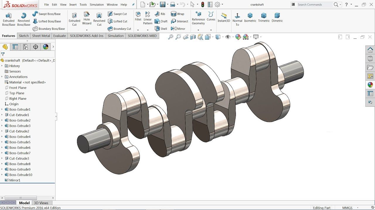
Solidworks Tutorial Crankshaft Youtube Solidworks Tutorial Solidworks Tutorial

Solidworks Tutorial Anvil Youtube In 2020 Solidworks Tutorial Solidworks Mechanical Engineering Design

How To Create A Mechanical Part Using Catia Part Design Surface Design Mechanical Design Design


Solidworks Weldments Tutorial Gusset Youtube Solidworks Solidworks Tutorial Sheet Metal Drawing

Solidworks Tutorial For Beginners Exercise 35 Youtube Solidworks Solidworks Tutorial Mechanical Design

Catia V5 V6 Tutorial Simple Lock Design Bolt Lock Tutorial Bolt Lock Design

Pin On Cad Practice
3
Source : pinterest.com
